My original transmitter was already on its tenth year of service when I first built this site back in 2002. If you dare to look at the source code you can see I was using layout tables (and still am! If it ain’t broke…). But the information spelled out below is new as of August 2020. You can also check out the old technical page and see how far I’ve come (Update September 2024: I’ve just replaced the antenna!). Enjoy, and best of luck with your own project!
The New Transmitter
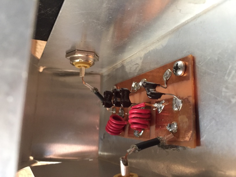
I must confess that I dragged my feet and put off the transmitter construction for a year and a half after getting the breakout board up and running. For one thing, I had not etched a copper board since the original. I even still had some ferric chloride from that project stored away, and tried working with it first! It wasn’t very effective. This gave me the chance to methodically assemble the parts and obtain fresh etching chemicals while I planned out every detail. When I finally embarked on the project in the summer of 2020, I built the simple harmonic filter pictured below first to practice my skills.
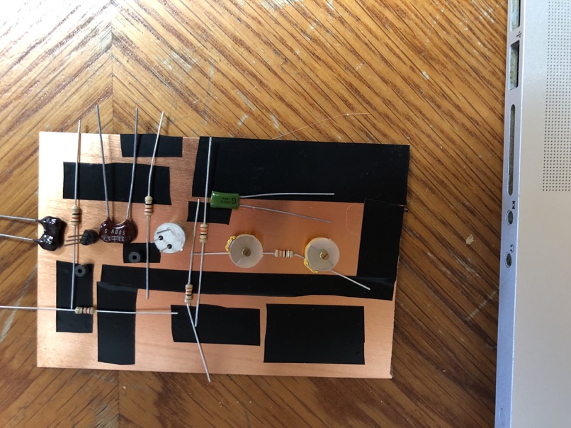
Satisfied with the result, I began the layout of the transmitter board. I decided to keep it simple and used the same electrical tape method I first tried on the filter board. I suppose if I were ever to mass-produce the boards, I would resort to creating a trace template and print it to iron-on paper to speed up the process, but that’s not my goal right now.
Here you can see the tape defining the traces for ground and power bus, along with the signal path components spaced to guide their eventual trace layout.
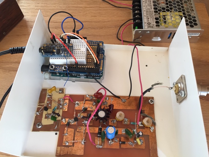
When I completed and tested the circuit, I discovered my 2-transistor amplifier’s power output was identical to the old transmitter. Below you can see the pre-amp I added on the left to achieve the boost I was hoping for. Note the breakout board’s original blue antenna wire feeding the circuit.
The Audio Chain
I’ve already mentioned that the new transmitter made the pre-emphasis, 19kHz notch filter, and stereo generator boards obsolete, because all these functions are built into the Si4713 chip. You could easily plug your iPod or mixer output directly into the breakout board and take advantage of the inline compressor, if you tweak the values for the code as I explain below. But I’ve had the dbx equalizer and Samson S-com plus compressor pictured to the right for a decade, so there was no point discarding them now. The Samson now acts as more of a slow gain rider than compressor, like an Aphex Compellor. A few equalizer band values were modified from what is seen here for a crisper high end and bass.
What can I hear on 101.5 FM?
The Arduino Code
The setup is explained thoroughly enough on Adafruit’s rundown. The code package is available on Github. I will only detail the changes I made to customize its operation and optimize the Radio Data System text display. Read up on the Si4713 Programming guide to learn about every facet of chip programming.
adaradio.ino
This is in the examples folder of the library. Besides setting the frequency and the power output, this is where you enter the RDS text. Scroll down to the comment ‘begin the RDS/RDBS transmission’ and find the radio.setRDSstation command. You can write a message the listener sees at once, but only 8 characters at a time. My message was written so:
101.5 FMLowPowerHighest Quality!
Because there are 32 characters, the message is sent in 4 parts, which is controlled in the .cpp file. Words longer than 8 letters need to be split into their first and last 8 letters, as in
Corporatorporate
so the whole word can be seen, which is weird and not recommended. Beneath that is the
radio.setRDSbuffer command. You can send a more elaborate message up to 64 characters. This is the song and artist info you see on most receiver displays, but note that
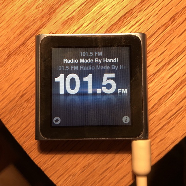
not all receivers read out the buffer. I had to use my iPod Nano to check for the buffer message, because none of my car receivers show it. And for more than a year, I struggled to get the buffer to display, even though it seemed to be working on the serial monitor readout. I attempted a number of hacks to get it to work, to no avail. It wasn’t until I read up on the protocol for Radio Text in the NRSC standards that I discovered any message less than 64 characters
must end with a line break character, or backslash r, like so:
The way radio should be, nothing but music\r
I still cannot believe what a simple solution that turned out to be. Moral: always read the manual!
Adafruit_Si4713.h
This file declares commands and parameters, not much to change here. The only items of note are the antenna capacitance and the RDS program ID. Scroll down and look for the line that begins void setTXpower. The antcap default is 0, which lets the board choose the value it thinks will work, anywhere from 1 to 191 (hint: it chooses poorly, to the point the board may not start up at all!). I found that a value of 22 gave me maximum range when the wire antenna was fully extended. The line void beginRDS just a bit further down includes the programID property, the FCC assigned call. The silly gang at Silicon Labs sets it to 0x40A7, which is for KSIL (a real station in New Mexico!), and Adafruit’s 0xADAF isn’t even valid. This page will let you find the proper hexadecimal code for any K### or W### US call sign if you want to change it. Query the FCC database here for an unused one.
Adafruit_Si4713.cpp
Unless you wish to use RT+, there are only a few areas in the C++ file that need attention: automatic gain and compression settings, pre-emphasis level of the audio processor, and RDS for text display. We’ll edit audio parameters first. Copy and paste this code snippet under the line containing the PROP_TX_ACOMP_GAIN parameter.
setProperty(SI4713_PROP_TX_ACOMP_THRESHOLD, 0xFFEC);//-20dB
I can’t overemphasize that audio processing should
always be on, else the signal will be unlistenable. This line isn’t in Adafruit’s code but is a function you should experiment with―just be aware the sum of ACOMP_THRESHOLD and ACOMP_GAIN values cannot exceed zero. A lot still depends on audio input level, so don’t go overboard. Make sure
both peak limiter and automatic gain control are on by setting the ACOMP_ENABLE value to 3 or 0x0003. The default here, strangely, is 2 (limiter only), disabling auto gain, and you’ll
really want that on! Finally, change _PREEMPHASIS to 1 (50µS) so audio high end doesn’t overclip the limiter.
Find the section containing TX_RDS_ properties. _MIX controls the ratio of station and buffer messages and defaults to 0x0003, which is 50%, or 1 to 1. My station message did not display long enough to show the whole thing before the buffer text replaced it, so I bumped it to 4, or 75% station to buffer. _MESSAGE_COUNT is determined by how many characters your station message has, divided by 8 plus any remainder. My station message above was 32 characters, so I set this to 4 (32÷8 and 0 remainder). Finally, take a look at _MISC. The default value of 0x1808 doesn’t tell you much, until you analyze the breakdown of bit switches it represents. Use a hex-to-binary converter to see 1808 in ones and zeroes. The result is a 13-digit number:
1100000001000
The one thing worth studying here is the location of the Program Type Code, which the Si4713 guide says is 5 binary digits in positions 5 to 9 (counting up from zero leftward). Refer to the table of program type codes below to obtain the correct binary value for your station programming (I chose Public, which is 10110, because 101.5 FM is both non-commercial and varies in format). Plug this into the correct location in the binary string and it changes to
1101011001000
which converts back to 0x1AC8. One of my car radios does not display buffer text but has a PTY button on the interface and briefly reads out PUBLIC when pressed. Fun!
Program Type Codes
| PTY code |
Binary |
RBDS program type (North America) |
| 0 |
00000 |
No program type or undefined |
| 1 |
00001 |
News |
| 2 |
00010 |
Information |
| 3 |
00011 |
Sports |
| 4 |
00100 |
Talk |
| 5 |
00101 |
Rock |
| 6 |
00110 |
Classic rock |
| 7 |
00111 |
Adult hits |
| 8 |
01000 |
Soft rock |
| 9 |
01001 |
Top 40 |
| 10 |
01010 |
Country |
| 11 |
01011 |
Oldies |
| 12 |
01100 |
Soft music |
| 13 |
01101 |
Nostalgia |
| 14 |
01110 |
Jazz |
| 15 |
01111 |
Classical |
| 16 |
10000 |
Rhythm and blues |
| 17 |
10001 |
Soft rhythm and blues |
| 18 |
10010 |
Foreign Language |
| 19 |
10011 |
Religious music |
| 20 |
10100 |
Religious talk |
| 21 |
10101 |
Personality |
| 22 |
10110 |
Public |
| 23 |
10111 |
College |
| 24 |
11000 |
Spanish Talk |
| 25 |
11001 |
Spanish Music |
| 26 |
11010 |
Hip Hop |
| 27 |
11011 |
Unassigned |
| 28 |
11100 |
Unassigned |
| 29 |
11101 |
Weather |
| 30 |
11110 |
Emergency test |
| 31 |
11111 |
Emergency |
Use an SDR dongle? Try RDS Surveyor to decode all RBDS/RDS data. You’ll need the Java development version, not the runtime, to make it work.
Radio Text+ How-to
Radio Text+ (RT+) is an RDS specification developed around 2005 to enhance the functionality of the 64-character radio text message. If a station is already labeling song and artist, along with displaying station ID and even business ads, in the scrolling text, RT+ can isolate those items on separate lines for easy reading. The Si4713’s programming guide only mentions how to add the radio text, station name, call sign, PTY code, and even a time signal. This involves calling up 3 of 32 possible groups that can contain information. The Si4713 guide leaves open the ability to use all 32 groups, but you must code this information without any further guidance.
Fortunately, the standard’s developers explain it in great detail here. All that’s left is to decide what you wish to display from your radio text...
101.5 FM Radio Made By Hand ...
...then code two new TX_RDS_BUFF commands below the existing one in the C++ file:
  // begin RT+
  _i2ccommand[0] = SI4710_CMD_TX_RDS_BUFF;
  // Define 3A ODA Group 12A AID 4BD7
  _i2ccommand[1] = 0x04; // Load new buffer into
  _i2ccommand[2] = 0x30; // Group 3A referencing
  _i2ccommand[3] = 0x18; // 18=Group 12A (24)
  _i2ccommand[4] = 0x0;
  _i2ccommand[5] = 0x0;
  _i2ccommand[6] = 0x4B; // RT+ app ID
  _i2ccommand[7] = 0xD7; // RT+ app ID
   sendCommand(8);
The comments explain each argument. We want to load new buffer text into Group 3A. This group defines all RDS Open Data Applications (ODA), of which RT+ is one. RT+ tags will appear in Group 12A, numbered as 24, or 18 in hexadecimal. The RT+ app’s ID code (AID) is 4BD7, split and loaded in arguments 6 and 7.
  // Define RT+ tags
  _i2ccommand[0] = SI4710_CMD_TX_RDS_BUFF;
  _i2ccommand[1] = 0x04; // Load new buffer into
  _i2ccommand[2] = 0xC0; // Group 12A
This one gets a bit more complex, so we’ll break it down line by line. Unlike argument 3 above, the second argument defines Group 12A as hex C0, as the second digit only toggles between A and B (0 or 1).
  _i2ccommand[3] = 0x18;
// 0001.1|000 Running 1, Toggle 1, Content Type 4(3)
Parsing the radio text begins in the last 5 bits of the second 16-bit block of Group 12A. The Running bit must be 1 for RT+ to display. After the Toggle bit are the first 3 of 6 bits setting Content Type 4 (artist). The pipe splits the binary string by element, while the dot splits by hex code, and the parentheses show how far we are into each element’s bit count.
  _i2ccommand[4] = 0x80;
// 100|0.0000 Content Type 4(6), Start 0(5)
  _i2ccommand[5] = 0x0E;
// 0|000.111|0 Start 0(6), Length 7(6), Content Type 1(1)
This fills the third block from the last 3 bits of Content Type 4 up to the first bit of Content Type 1 (song title).
  _i2ccommand[6] = 0x09;
// 0000.1|001  Content Type 1(6), Start 9(3)
  _i2ccommand[7] = 0x32;
// 001|1.0010  Start 9(6), Length 18(5)
   sendCommand(8);
This fills the fourth block from the last 5 bits of the Content Type 1 element through the 5 bit Length element. See the result on my iPod nano at left. Double fun!
