Here it is: the left brain solution to the right brain's desire to bring a little sanity to our lives...more machinery! Perhaps you should just go out and buy an iPod...no? Well, then, pay close attention and see how I pulled off this unlikely technical marvel. This is laid out in the order I put everything together, how this sort of accreted little by little until I became satisfied. I'm not a technically savvy individual, though I enjoy problem solving and taking things apart to see how they work. My first obstacle to getting on the air became, rather obviously, building the transmitter. Once its dependable operation was assured, getting out of my backyard with a decent antenna came next, then stereo separation and a crisp clean sound...
In the event you already have a station, or want to satisfy your own curiosity about what I put into my system, I offer this list of links to each step in the process of making 101.5 FM what it is today.
This page is still under construction but is closer to the finish line than the start. More is forthcoming on audio processing, my plodding quest to update my old transmitter, and adding a compressor/limiter for a louder signal.
Late in the evening, a few minutes before Columbus Day, 2006, I took the transmitter down for an antenna overhaul. After signing back on around midnight, the transmitter ran continuously for 259 days, with only several minor adjustments to oscillator frequency in that time. The transmitter, to look at it another way, stayed on the air through at least part of all four seasons — rain, sleet, snow, wind, heat — and never wavered.
The antenna overhaul involved connecting the coax to the antenna with 3/4 inch copper straps instead of the coax conductor wire itself. This allowed greater flexibility in tuning the antenna and lowering the SWR from about 1.7 to 1.4, while also stabilizing the overall load, especially during periods of precipitation. So without further ado, here's the transmitter schematic in pdf of the best 3-transistor bug on the planet, bar none.
You can't last the long haul on AA alkalines!! Here are the power supply schematics for transmitter and audio processing.
Beaming a 1/10 watt signal a mile, and they said it couldn't be done.
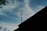
My first antenna (left) was a ground plane made from an SO-239 connector and five lengths of 14-gauge copper wire. It worked pretty well...until the wind blew. Nothing changes load impedance, and thus frequency, like changing antenna dimensions. So after building Marconi's Slim Jim antenna and getting mixed results from an eave-mount, I modified the width of the PVC pipe to couple with the plumbing extending from my rooftop, allowing me to raise the radiation center seven feet and move it farther from a large tree. For some reason, the resultant load was over 50Ω, presented a ratio of 1:1.7 on my SWR meter, and resonance at 107 MHz. I let sleeping dogs lie, since I still saw improved coverage.
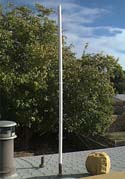
The best thing was the rigid design helping the antenna maintain a constant load impedance, a must for a transmitter with a free-standing oscillator. When I changed frequency and cut a new antenna from 18-gauge solid wire, I was able to achieve resonance where I wanted, and lowered the VSWR slightly as well. Keep your guy wires attached below the halfway point of the pipe for a more omnidirectional radiation pattern.
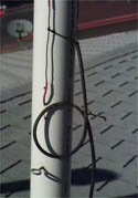
At left is a detail of a choke balun. Unbalanced antenna current will flow unimpeded back to the transmitter ground. This choke presents a high resistance to this current, effectively blocking it from traveling back down the ground braid of the feeder cable to cause problems with reflected power and increased SWR ratios. Another balun is placed 1/2 wavelength down for more effective suppression.
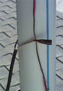
To tune your antenna you must have some method of measuring SWR (standing wave ratios). After connecting this device to your transmission line, clip the center conductor and ground braid to the bare copper wires (right) and slide up or down to achieve the lowest possible SWR, then solder in place. Not only will a tuned antenna mean more power, but a vastly improved sound, especially when broadcasting the complex stereo baseband.
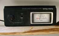 To continue monitoring both forward and reflected power, I placed this modified SWR meter in the line, which also helps buffer the transmitter from weather-related load changes like rain and snow. To accurately measure my low output, I replaced the 3.9kΩ resistor in the forward circuit with a 1.5kΩ.
You mean it is possible to build a decent stereo generator from the infamous BA1404 chip? Yes, it can be a struggle, but it's worth it. However, you need to modify it in a couple of ways.
First, get your kit, available from Jameco.com. It'll cost you $30 plus S&H. If you've already gotten one, you've undoubtedly noticed it isn't quite up to the task of working as a stereo generator, much less an FM transmitter. When I first turned it on, the pilot lamp glowed on my receiver, but separation was non-existent. Furthermore, its ability to handle high end audio was a joke. Any energy present in the 19kHz spectrum nulls the pilot tone and kills the stereo signal, symptomized by a blinking stereo lamp on your receiver (and some godawful distortion). Armed with the schematic and my scope, I soon discovered two quick fixes. One: removing the 150 kΩ resistor at pin 13 kept the pilot output there from interfering with its twin in the composite output from pin 14, and some separation appeared. The chip's technical manual states that the components it recommends at these two pins' output should not be changed, or the pilot will not be in phase. Perhaps that is the case when these components have no tolerance for error in their working values, but high-priced capacitors and resistors definitely don't come with your kit. Two: replacing the .001 microfarad capacitors in the passive pre-emphasis circuit with 330 picofarad caps reduced the presence of 19kHz audio, but at the cost of high-end overall quality.
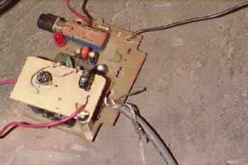
However, the RF side of the kit was unacceptable: impossible to accurately tune, low output with lots of harmonics, etc. I removed the oscillator and coupled the composite output directly into my existing transmitter. Here came my third discovery: reinjecting the pilot with some control over its amplitude allows you to control the loudness of your audio signal without compromising the integrity of the composite signal. Therefore, the modification you see in the schematic and the tiny board add-on in the photo below. Simple, but it really works!
For best results, you should build my 19kHz notch filter. This will eliminate any 19kHz audio energy, preserving both high-end and integrity of the stereo signal. Center the notch at 19kHz with the variable resistor.
How to sound better than stations with thousands of dollars of equipment...for just pennies a day!!
The passive 330-picofarad pre-emphasis circuit mentioned in the previous section made for a stable stereo circuit, but put my high-end in the ditch. Eventually I came across AMN's active pre-emphasis module and got around to building it. It didn't work at first, until I realized ground potential is not the same as negative voltage.
Once I built the bipolar power supply and hooked it up, everything was fine. More than fine, actually. The treble was so prevalent I actually dropped the 12kHz sliders on my mixer EQ to minus 4 decibels. The roll-off above 16kHz was not enough, though, to keep 19kHz energy away from the pilot, necessitating the addition of the notch filter mentioned above, and the replacement of the 470-picofarad capacitors in the final stage with .001-microfarads.
Here is the schematic, readily available elsewhere, for Free Radio Berkeley's transmitter. Should you choose to build it, you will also need to check out these items:
Building it is not for the faint of heart...I haven't even tried to build it yet. The biggest obstacle is etching the copper board to such exacting specs as will fit the legs of the PLL chip. I attempted a method using a laser printer and the back of a sheet of photo quality paper. This is best described on AMN's page on the subject. I tried it once with somewhat promising results, but not good enough to finish the project. However, the Motorola chips I ordered were lost during a move and, sad to say, are no longer on the market.
My printed circuit board template for a 3x4.5 inch circuit board.